ESP32 Project #2: Digital Input & Output
Hello! I’d like to tell about my second ESP32 Project, Digital I/O. If you wanna read my first post please kindly read here.
ESP32 has input pin and output pin as interface to communicate with others. These pins are called GPIO (General Purpose Input Output). ESP32 has default pin for any kinds of interface. Some pins could be changed, depending on the program code. For reference, you can access what are ESP32 pins here.
Digital I/O
On this project, I’ll show you how digital I/O in ESP32 works by using push button. When the button is pressed, the LED is supposed to be on. Okay, before jumping to the project, I’ll show you what components will be needed on this project.
Parts and Components
- ESP32 Board
- Breadboard
- Male to male wire
- LED
- Push button
- 330 & 10K Ohm resistor
- USB cable (I use my Android charger)
After preparing the parts and components, we’ll follow this shematics.
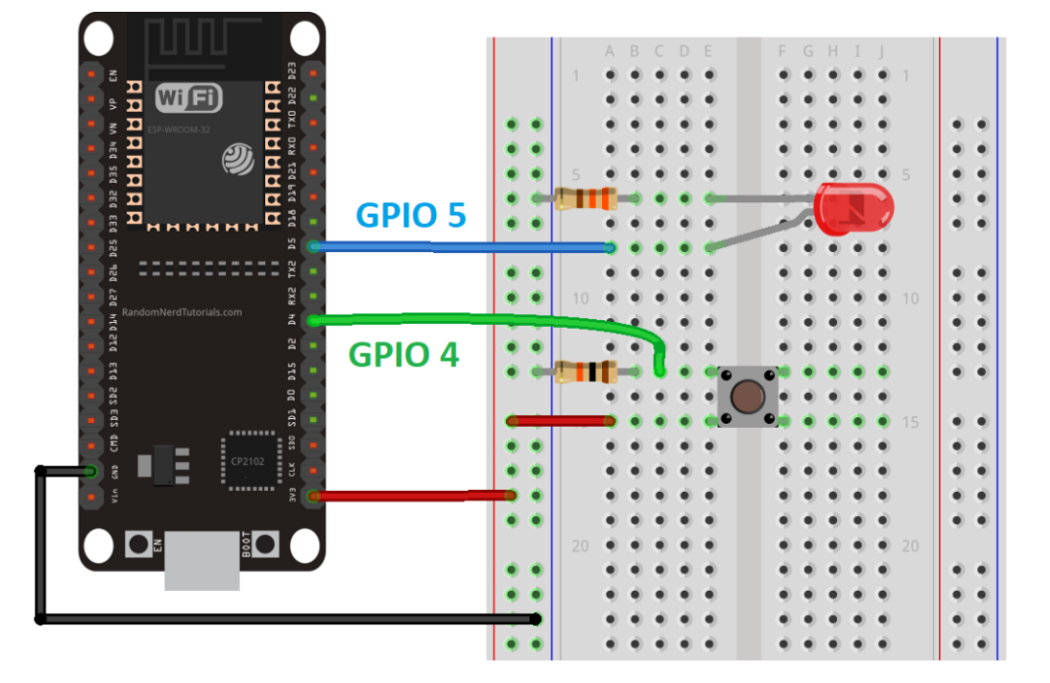
I connect the 3v3 to the negative part of the breadboard, while connect the positive to the ground. I only used 1 LED for my first trial. I connected it with a male-to-male jumper wire to GPIO 5 with 330 Ohm resistor. The shorter LED leg is cathode (-) while the longer is anode (+). I put the push button as shown on the picture above, connected with a male-to-male jumper wire to GPIO 4 with 10K resistor.
I found something strange happened. My ESP32 was suddenly hot and the LED was not working. I checked it and found I put the wrong resistor :).
This is my real schematics.

This schema is from tutorial provided by my lecturer so I wanna try it first. Will it work?
Code

First I initialized the number of GPIO I used for the LED and the button. It was 4 for the button and 5 for the LED. Then the push button status was set to 0 (when it is not pressed). On the setup() where this would be run only once, we’ll see Serial.begin(115200), that means the baud rate is 115200 bits per second bits per second. Then we’ll set the push button as the input and the LED as the output.
On the loop(), we’ll read the input (push button). If the buttonState is HIGH (the button is pressed), the ledPin will be written HIGH (the LED will be on), and vice versa.
Since there is Serial.println(buttonState), the button status will be printed on Serial Monitor on 115200 baud. It is digital so 0 and 1 will be printed.

First Trial
My first trial was when I couldn’t put it safely in the hole. The code didn’t work and first I thought there was a problem on my jumper wires. I changed the wires and nothing happened.
Then, I realized the ESP32 was not connected properly to the breadboard. Trying to fix that, I got a bad experience when I used my strength and hurt my finger.

Now it won’t fall when it’s turned.

Second Trial
Finally it worked! I pressed the button and the LED was on, then turned off when I released it.

Another Schema
I followed the provided tutorial for testing if it really worked, then I tried another schema for my exploration. For this trial, I used 2 LEDs and 2 push buttons.

Of course the code changed.

I put the second LED on GPIO22 and the second push button on GPIO23. For that, I added more variables and modified the setup() and loop(). The first LED should be switched on when the first push button is pressed, the same as the second LED. We can press it together and both of them will be on.

Voila! It worked!
Analog I/O?
Can I do experiment about analog I/O? I don’t have a potentiometer so I’m not sure about that. I’ll explore more about that :).
Final say
I got bad and good experiences through this project. Before I didn’t always put my ESP32 on my breadboard since it won’t stick, but the LED won’t be switched on if the ESP32 is not connected. So, I used all of my strength to force it and something bad happened. But it’s okay since my ESP32 is already on my breadboard and I won’t mess up with that anymore XD.
See you on my next projects!